Overview
Settings
When MapBoards (MB) is first installed, there are default settings. When you invoke MapBoards on a model, the Lumber tabs will display a list of Board Types found in the model. A board type is the pairing of material type and board thickness. Material type refers to either the physical material or the appearance base selected in Use Appearance, found in the options tab. With each board type there are two dimensions, width and length, which will be used as the default board size when creating a map. The first time a material type is encountered these values will be set large enough to accommodate the largest component of that board type. The Options tab will reveal these default settings. If you make any changes to these default dimensions or settings, they will persist the next time you invoke MB on this model.
If you want the current settings to be the default on all models being opened for the first time, you can press the Save as Default button in the Options tab. In addition to making the settings in the Option tab the default, it will also make the board type dimensions the default for the respective board types.
Board Dimensions
The dimension settings for each board type, Width (vertical Y direction) and Length (the horizontal X direction), define the default targeted boards dimensions. When MB is run, it will create enough boards with these dimensions to accommodate the mapping of all the component bodies matching this board type. You should configure the orientation, either portrait mode (larger width) or landscape mode (larger length), to match the targeted machine you will be manufacturing your model on.
Board Arrangements
Boards are arranged using one of three arrangement types available in the Arrange Type option. This allows you to match your needs for rip cuts, cross cuts, or a more random diagonal fill pattern. These arrangements are NOT true nesting, but they are optimal for most users and can be performed reasonably fast. The placement is done using a tight bounding box around each component with options for component spacing and a reserved edge on boards.
Grain Direction
When MB arranges components on a board it will align the long edge of a component with the targeted board’s long edge as the default, with the following exception:
If the option Can Rotate is selected, a component may have its long edge rotated perpendicular to the targeted board grain direction. This will only occur if it would better utilize space or if none of the remaining components would fit an available space with the component long edge and board grain aligned.
Modifying Created Map
Once the map is created, you can modify the location of a component within or between boards by doing the following:
Click on the Top face of the orientation cube
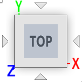 located in the upper right corner of the window to align the map facing
forward. You can then slide the component to the desired location within or between boards.
located in the upper right corner of the window to align the map facing
forward. You can then slide the component to the desired location within or between boards.
What’s Next
That is the general overview. Try things out on some simple models. You can browse the table of contents in this document or use the Quick Search option to find a description of an option or a topic of interest.